Last Updated on November 29, 2020 by technoreview85
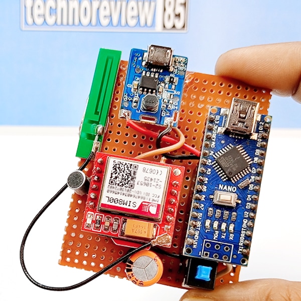
In this article I am going to tell you how you can make a spy bug audio surveillance listening device using Arduino.
Using this mini device you can listen audio from anywhere using gsm network. you can record this audio on your phone so it is a gsm bug spy listening device.

How it’s works
It is a gsm based device so you need to use a 2G network supported sim card in Sim 800L gsm module.
place the device where you want to surveillance & call the inserted sim card number ( mobile number).make sure you have sufficient credit balance in your sim number for receiving a call. you can hear ringing sound on your mobile but the device does not make any sound & it automatically receive your call. now you can hear the sound from device microphone or you can record the audio on your mobile. you can hang the call anytime. it is a spy device so it doesn’t make any sound or light indication.
this device has long standby time & call time also, it depends on how many amp battery you are using for this device.
you can charge the battery of this device using any smartphone charger.
You need to make
- Capacitor 470mf/25v
- Condenser mic
- Resistor 10k & 3.9k
- Dpdt switch (small)
- Power bank module
- Arduino nano
- Sim800l gsm module with antenna
- Dotted Prefboard
- Female header pin
- Any old phone battery
Making
Insert all parts on the prefboard. I have used female headers for arduino nano & Gsm module.

Schematic diagram

I am using a power bank module for Arduino 5v supply & it can also charge the battery.
Connect USB + 5v to arduino vin pin via
Switch & connect the battery to power bank modules B+ & B-
Don’t connect sim 800l to 5v
Connect it’s VCC to 3.7v battery via the switch.
Gnd to the battery negative (-)
Arduino D4 pin connected to RING pin of GSM module.
Uploading code to Arduino
Remove arduino from prefboard & connect it to a computer then upload code to arduino nano
you can download the Ino file from bellow or copy the code & paste to a newly created file on arduino IDE.
int PIN = 4;

int sensor ;

void setup() {

pinMode (PIN,INPUT);

Serial.begin(9600);

delay(5000); }

void loop() {

sensor = digitalRead (PIN);

if (sensor == LOW){
delay(1000);

Serial.println("ATA");


delay(1000);


 }
}
Some Interesting projects
- Obstacle avoiding robot
- How to make a 3d printer with arduino
- GPS Tracker – How to Make a Tracking Device for Car or Bike


great looking