
In this article, I am going to describe how you can build a very useful assistance device for a blind person. This is an Atmega 328p microcontroller based project. This circuit has two sensors which are ultrasonic object detector sensor & light sensor.
How it works
It will detect the object from about 2ft away & the beep sound will be changed according to a distance of the object. If the light is very low then the buzzer will beep once per second.
So it is possible to gauge the distance & Light condition by hearing different beep sound. It will also work in complete dark condition
You can make with it a smart glove or you can install it on a regular blind stick.
You need to make
- Resistor – 10K, 330E
- IC 7805
- Ceramic capacitor 22pf – 2pcs.
- Ceramic capacitor 0.1uf
- Electrolytic capacitor – 47uf/63v
- LED
- 5V Active Buzzer
- LDR
- 4mm SPDT switch
- 16 MHZ Crystal
- HC SR 04 Ultrasonic module
- 28 pin IC base
- atmega328p
- Terminal block
- Female header pin
- PCB ( from pcbway.com )
- Plastic or acrylic sheet
- Gloves
- 9 Volt battery or mini power bank
How to get PCB For this project
I have designed a circuit & make it in a PCB. You can download the PCB Gerber file from here. Then upload the Gerber file to pcbway.com
Pcbway is a world-leading PCB manufacturing company & they provide excellent quality PCB at a reasonable price. the 10 PCBs cost only 5$ (without shipping charge )
For order PCB just go to www.pcbway.com
Upload Gerber file which you have downloaded.
You can check your PCB price using Instant Quote. If you want to order then you have to create an account in pcbway & log in to your account. fill your address in your account then set some parameters like size, silkscreen colour etc. select shipping currier & place order.
Here are details about how to place an order in PCBWAY
Pcbway makes PCB quickly ( Build time 24 hours for 2 layer PCB) so you will get it soon depending on your Courier selection.
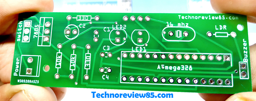
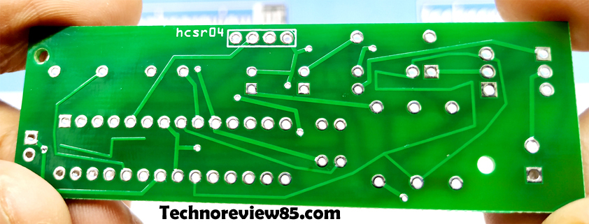
Assembling of components
The assembling of components is very easy. All components value, polarity is printed in the PCB so just follow the printed components on the pcb. Use a four-pin female header pin for HC SR 04 ultrasonic module, after assembling just connect power to the terminal block. You can use a 9V battery or mini power bank or any other battery fore than 5 volt.
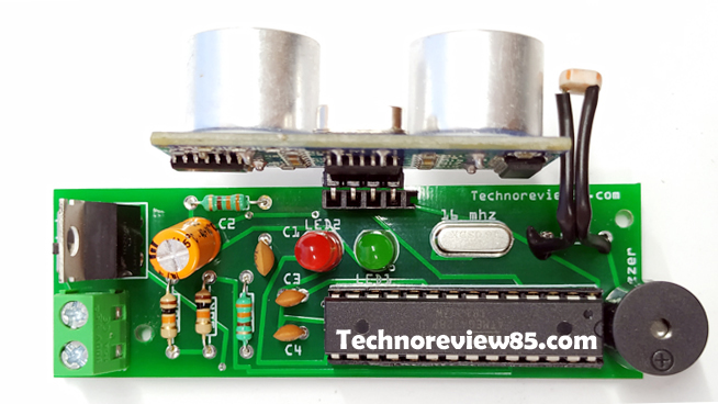
About the circuit
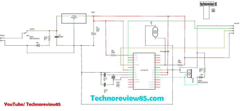
This circuit working with microcontroller Atmega 328P with Arduino boot loader. IC 7805 used for supply power to microcontroller & sensors. It is a 5volt regulator IC. For light-sensing, I used an LDR & The ultrasonic sensor used to the detect object.
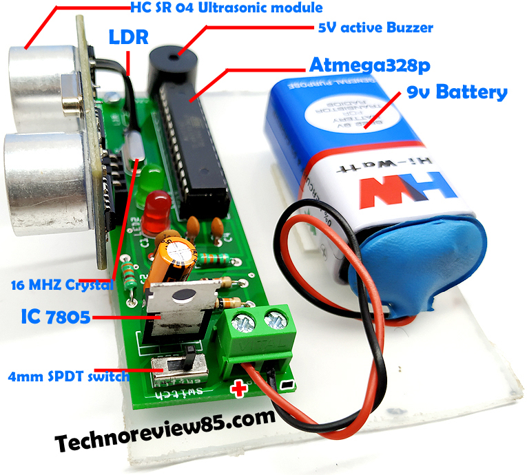
The above picture shows all components & power connection
Schematic of this project
How to program Atmega 328P microcontroller
It is very easy to program this microcontroller. Just remove the microcontroller from Arduino UNO board. Make sure the microcontroller which one you are going to use, it is pre – Arduino boot loader loaded. Upload Arduino code to Uno & remove it again from Uno then insert to the project PCB,
For the test, you can use an Arduino UNO board’s Atmga 328P. After code uploaded just insert it to project PCB.
Upload the code
Download the code from here & upload to the microcontroller using Arduino IDE software.
Video Tutorial
https://www.youtube.com/watch?v=_fnX7B-P304&feature=youtu.be
how i can edit the pcb file ?
how i can edit the Gerber file i try to edit it with many apps like eda but it’s not working