
Using this 433mhz radio-controlled remote circuit you can make different types of projects. You can implement it as a wireless controller for robotic projects, Remote Control car, control electrical device like light, fan etc.
Today in this article I am going to describe you how you can make a long-range RF remote control transmitter & receiver circuit.
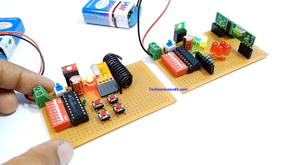
For making this remote circuit we have to make two deferent circuit on pref board or vero board. One is transmitter & another is the receiver.
Making The transmitter circuit
At first, I will tell about the transmitter circuit
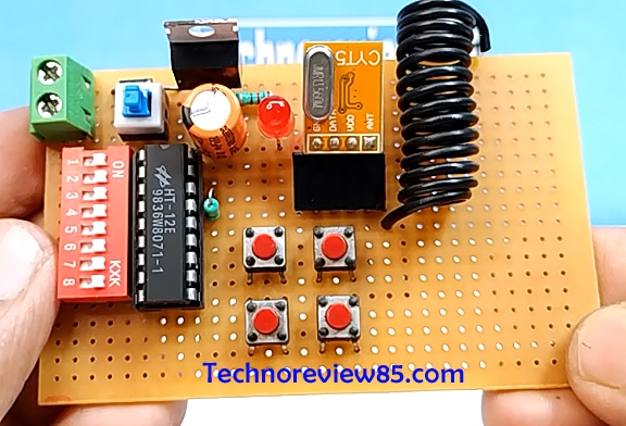
You need to make this transmitter part
- Diode 1N 4007
- Ceramic capacitor 10kpf
- Electrolytic capacitor 100mfd
- Resistor 200Ohms, 470k
- Led
- Ic 7805
- HT 12E
- 18 pin ic base, it is optional
- Micro push-button switch
- Push to on switch
- 16 pin Dip switch
- wire for Antena
- Vero board
- 2pin terminal block
- female header
- 433 MHz rf Rx, tx module
For the transmitter, we need only the Tx module & it is for the receiver.
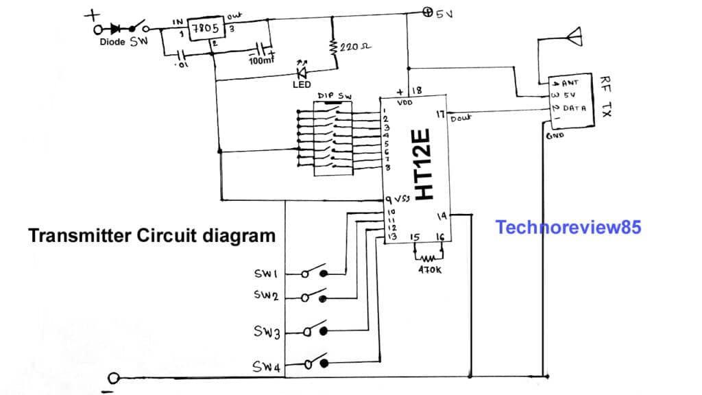
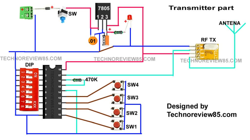
Construction
Ic pin 1 to 8 connected with dip switch
Pin 18 is 5v supply & pin 9 is gnd
Pin 17 is connected to tx module data pin.
Now insert all components into the Vero board.
Connect them like connection diagram
Transmitter circuit diagram
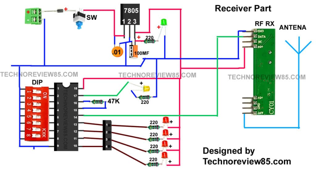
Circuit diagram using practical components for beginner
The transmitter part is ready. now you need to make the receiver.
Making The Receiver circuit
You need to make the receiver part
- Diode 1n4007
- Capacitor 10kpf, 100mfd
- Resistor 220ohm 6 pcs, 46k
- RED Led red 4 pcs
- Yellow LED
- Green LED
- Ic 7805
- Ht12D
- 18 pin ic base
- 1 push to on switch
- 16 pin dip switch
- 433 MHz rf reciver module
- 2 pin terminal block
- header pin
- Vero board
- And wire for antena
Construction
For transmitter we used ht12E
But here for receiver, we are using ht12D
Ic pin 1 to 8 connected to dip sw
Pin 18 is connected to 5v & 9 is and
Pin 14 is connected to the Rf reciver module data pin
Insert all components & connect them
Receiver circuit diagram
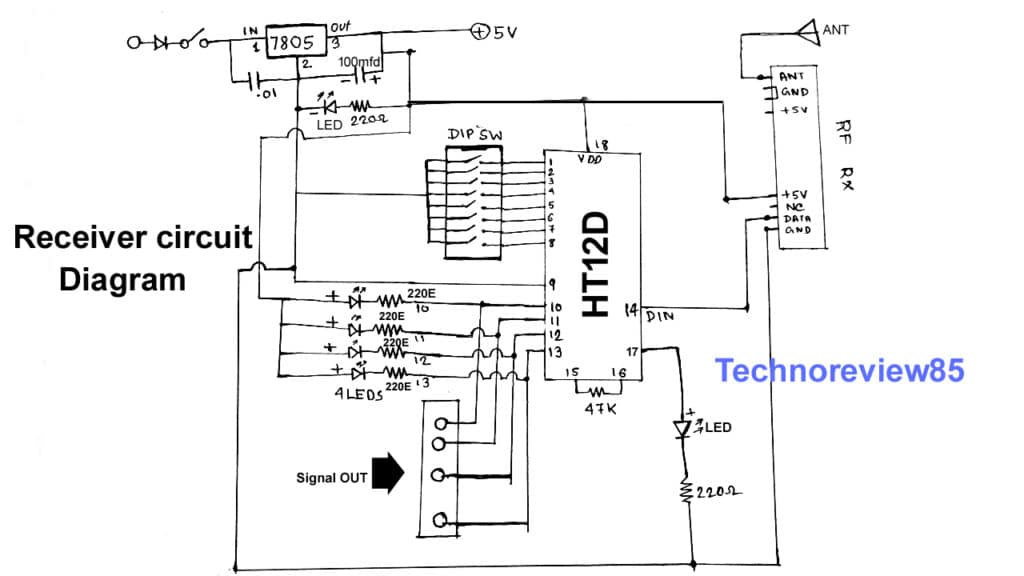
Circuit diagram using practical components for beginner
Now our both circuits are ready
As an antenna for both circuits, I am using
Some hookup wire about 10 turns.
You can use a telescopic antenna also.
For power, you can use 5v to 12v
I am using 9-volt battery
you can see 8 switches on the DIP switch
Turn on or off the same number of switches in both circuits. If the transmitter switch is on, you need to on the receiver switch at the same position.
It is for pairing with this particular transmitter with this particular reciver
Like a combination lock. It will very useful when you will use multiple transmitters & reciver within the same working range.
Very good
very helpful thanks
I am so happy to have found this document and the video. So many thanks.
thanks for great content