Last Updated on January 7, 2022 by technoreview85
It is a simple electronic project using an Ultrasonic sensor HCsr 04 with IC 555.
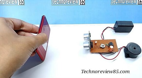
Usually, we use HCsr 04 ultrasonic sensor with Arduino. But if you want to make a simple object detector without any coding & any complex connection then this circuit will be very helpful for you. It is a simple electronic project with Ic 555 without any microcontroller or Arduino.
How it works
Normally hcsr04 has a sound transmitter & a receiver. In Arduino based ultrasonic range finder, we send a PING sound wave using a transmitter of HCSR04 after that the PING is returned by reflecting any object & the receiver detect this. Then Arduino calculates how many times take it to return & measure the object distance from the ultrasonic sensor. All the processes work with an Arduino code & it is a digital way.
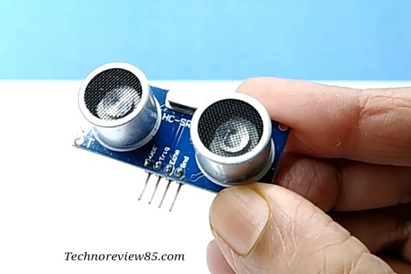
But in this simple electronic project, we are just sending a signal which is generated by IC 555 & receiving its reflection by the receiver of HCSR04.So you can hear the reflected signal wave which you are sending from the transmitter of HCSR04.
This circuit can’t measure the distance it only makes a sound when an object is in front of it. It is an analog way so no need for any microcontroller or Arduino.
Its detection range is near about 12 inches. You have to adjust the preset for a better experience.
You need to make
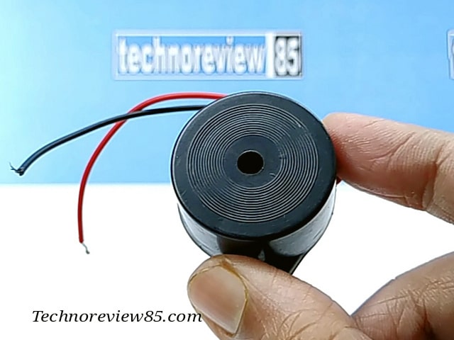
- Active Buzzer (passive buzzer will not work)
- Perfboard
- Electrolytic capacitor 10mfd/25v
- 100mfd/25v
- Ic 555
- Resistor 1K
- Potentiometer 10K
- Ultrasonic sensor Hcsr04
- 4v battery or any 5-volt power source
Connection details
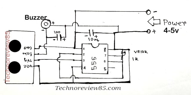
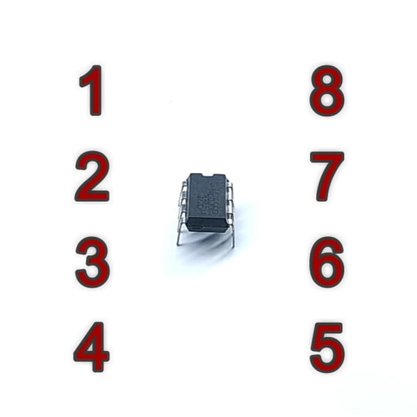
Ic pin 1 is connected to a battery negative.
Ic pin 4&8 connected to the battery positive (4-5v)
Ic pin 2 & 6 is connected & 1K resistor is connected to ic pin 6 & 7.
Potentiometer 10k is connected between Ic pin 7&8.
10mfd capacitor is connected to ic pin 1&8.
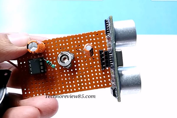
Hcsr04 echo pin is connected to active buzzer negative.
Hcsr04 trig pin is connected to ic pin 3
Video Tutorial
For better understanding please watch the project video.

I can hear the pulse at all times and then the alarm when I place something in front of it. How do I prevent hearing the pulse and only hear the alarm when an item is placed in front of it?
Adjust the Potentiometer
do you have the curcuit on the breadboard . if u have it pls emaill me
Still not working 😭😭
I need a project report on this project
What can I add to this circuit to measure it as well???