
In this article, I am going to describe how to make a mini regulated DC power supply easily.
Using this Ac to Dc regulated power supply you can get any voltage between 1.2 v to 12 v
You can use it to provide power
Of almost any electronic circuit & gadgets which is works with 1.2 to 12 v.
It is very useful as a mini-lab power supply.
You can also charge batteries using it.
You need to make:
- Step down transformer 0-12
( The primary input of this transformer is 220v or 110v ac
As per your country ac supply.
The secondary or output of this transformer is 0-12.
You can use up to 1 amp transformer )
- Ac main cord
- Wire
- Crocodile clip
- Power supply cabinet or any plastic box
- Dc voltmeter unit (3 wire)

- 5k potentiometer
- Capacitor – 1000mfd/25 v, 100mfd/25v, 0.1Mf( ceramic )
- IC – Lm317, 7805
- Diode – IN 4007 – 4 pcs
- Resistor – 220 ohm
- Screw & heat sink for lm317
- PCB. from pcbway.com ( download & order PCB from here)
How to get PCB For this project
I have designed a circuit & make it in a PCB. You can download the PCB Gerber file from here. Then upload the Gerber file to pcbway.com
Pcbway is a world-leading PCB manufacturing company & they provide excellent quality PCB at a reasonable price. the 10 PCBs cost only 5$ (without shipping charge )
For order PCB just go to www.pcbway.com
Upload Gerber file which you have downloaded.
You can check your PCB price using Instant Quote. If you want to order then you have to create an account in pcbway & log in to your account. fill your address in your account then set some parameters like size, silkscreen colour etc. select shipping currier & place order.
Here are details about how to place an order in PCBWAY
Pcbway makes PCB quickly ( Build time 24 hours for 2 layer PCB) so you will get it soon depending on your Courier selection.
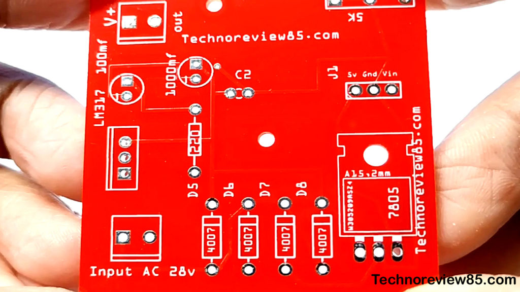
Assembling of components
The assembling of components is very easy. All components value, polarity is printed on the PCB, so just follow the printed components on the PCB.you can install the potentiometer on the PCB but I use two wires to connect the 5k potentiometer for easily install in power supply cabinet.
Parts have to install in PCB
- Lm 317 ic
- 7805 regulator ic
- 220ohm resistor
- 1000mfd, 100mfd, 0.1Mf capacitor
- IN4007 – pcs.
- 5k potentiometer.
Circuit diagram
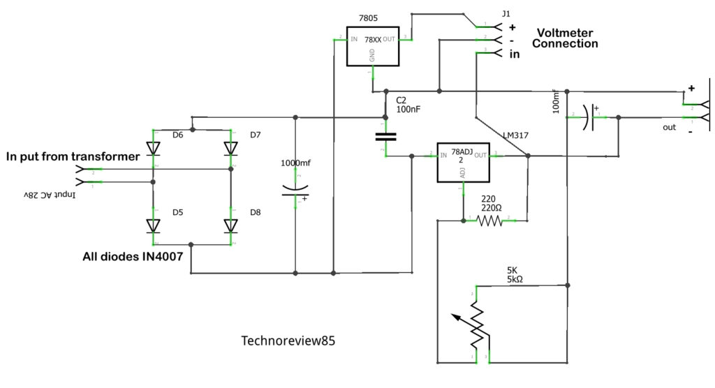
About the circuit
The lm317 is used for the voltage regulator.
4 In 4007 diode working as a bridge rectifier. capacitors used as filters of dc voltage
The 7805 voltage regulator used for supply power to the voltmeter unit this voltmeter unit can measure up to 100v dc but the unit runs on 5v
So the voltmeter unit has three wires red for 5 v +
Black for GND
& another wire yellow is for measuring the voltage. (V in)
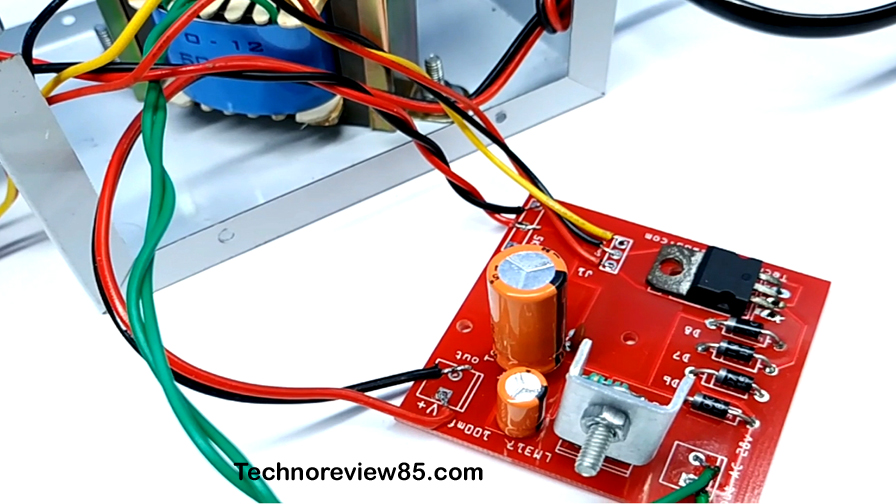
Fitting the transformer in the cabinet
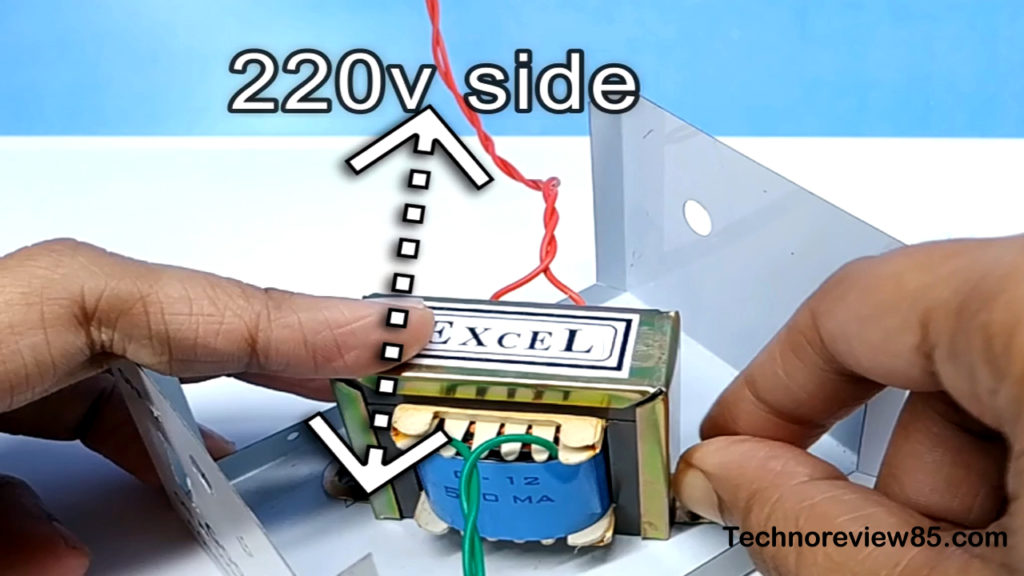
You have to fit the transformer
Inside the cabinet using 2 screws & join two wires of ac main cord into primary(220v) wires of the transformer.warp the wire using tape.
Important: join carefully the transformer proper input & output wires. You can find written on the transformer 0-12 & 220. If you connect wrong wire it may burn.
This transformer output & input have not any polarity, it produces ac voltage. Basically, it converts ac 220 v to ac 12 v.
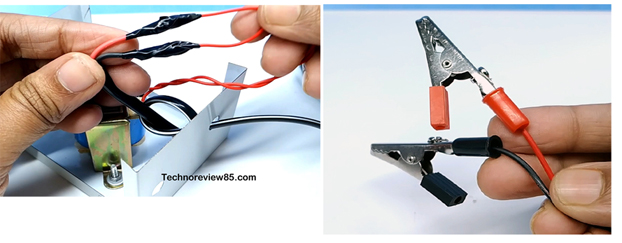
Connect crocodile clips in voltage output wires. Now connect voltmeter, Dc voltage output wires, 5 k pot & transformer output wires in PCB.
As the connection diagram below (also printed all on PCB)
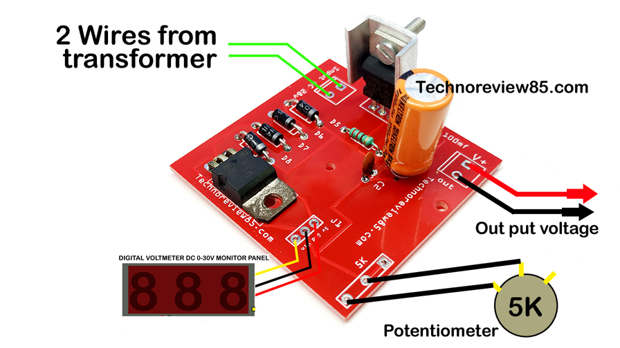
Now use some plastic or any other none-conductive material to warp PCB & install it in the cabinet.
Now it is ready for use.
Important: use a bigger heat sink on IC LM 317 if you are using heavy load like a motor otherwise the ic will be hot & stop working after some time.
Feel free to contact me using comments if you have any questions or suggestions.
Hello there, I found your site via Google while searching for a related topic, your website came up, it looks good. I have bookmarked it in my google bookmarks.