Last Updated on February 27, 2022 by technoreview85
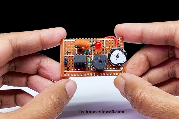
In this article, I am going to describe how you can make a human heartbeat monitor circuit.
Usually this type of project we can make using Arduino or other microcontroller but here I didn’t use any microcontroller so no need to code or program. I think it is a very interesting project for beginner electronic project lovers.
Here I designed a special connection diagram, which is especially for my friends who are new to making electronic projects.
Every component is with real parts, not traditional symbols so I think it is very easy to understand.
Working of the circuit
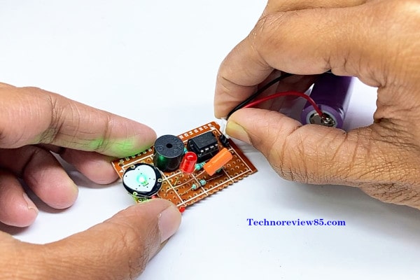
This electronic project circuit is designed with a dual operational amplifier IC lm 358.
It is an 8 pin IC.
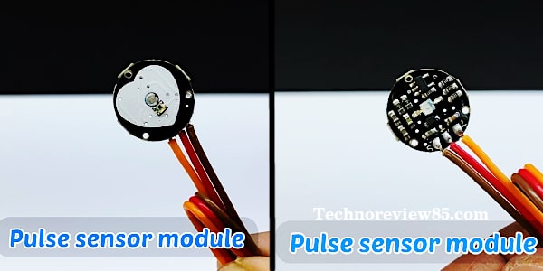
We are going to use the Arduino Pulse Sensor module to sense the pulse from the finger. This sensor gives an analog signal to the input of the Ic.
The output of the Ic is connected with an active buzzer + and a Red LED which is used for indication of the heartbeat.
How to use
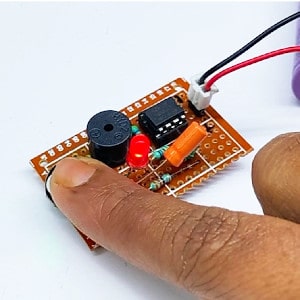
You have to put your finger on the pulse sensor. Sometimes it takes a little bit of time to recognize the pulse. When successfully recognised the LED will glow by the rhythm of your heart & the buzzer beep according to your heart bit.
You need to make
- Capacitor 4.7mfd
- Red LED
- Resistor 47K, 6.8K, 680K,330 ohm
- Ceramic capacitor 100k of
- Active buzzer
- IC Lm358 & IC Base
- Dotted Board
- 3.7 volt Lithium Battery & 2 pin header pins.
- Pulse Sensor module
Circuit diagram
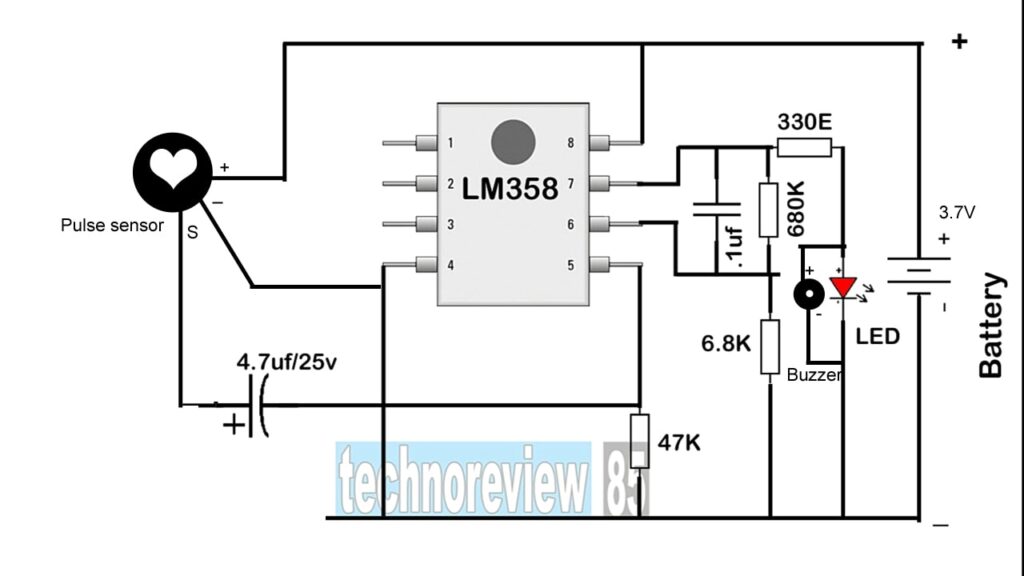
Connection diagram
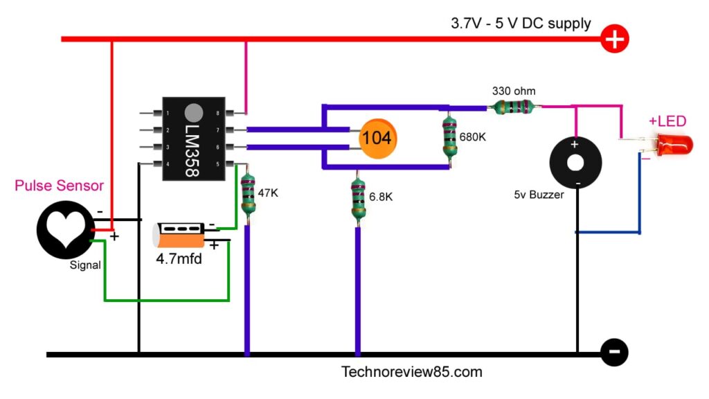
Insert all components to the dotted pcb. follow the circuit diagram for connection.

good working
very happy to know. thanks
Hi, how much volts did you used in pulse sensor module? thanks
here I have used 3.7v. The sensor works from 3.3v to 5v
Hi, can you simulate your circuit on proteus 8 pro? i have been trying for 2 days but still fail to do that. Thanks