Last Updated on September 5, 2020 by technoreview85
In this article, I am going to describe, how you can make a dual-tone electronic doorbell.
For making this project I have used very popular timer IC 555.
When you press the button then the IC generates a tone & after release, the button The IC generates a different tone so it’s sound like a ding dong bell.
You need to make
- Small speaker
- Capacitor 10 mfd /25v
- Capacitor 100 mfd/25v
- 47K resistor – 4 pcs
- Diode IN 4148 2 pcs
- Ceramic capacitor 0.01uf – 2 pcs
- Ceramic capacitor 0.001uf
- Microswitch
- terminal block – 2 pcs
- IC 555
- 8 pin IC base
- 4 X AA batteries & battery holder Or any DC 6v power source
- Wire
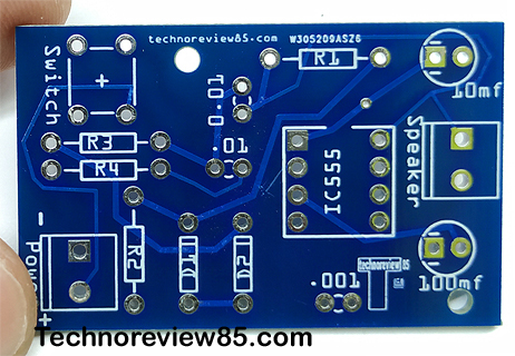
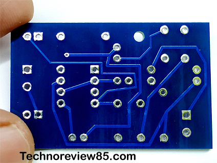
- PCB ( from pcbway.com )
How to get PCB for this project
I have designed a circuit & make it in a PCB. You can download the PCB Gerber file from here. Then upload the Gerber file to pcbway.com


Pcbway is a world-leading PCB manufacturing company & they provide excellent quality PCB at a reasonable price. the 10 PCBs cost only 5$ (without shipping charge )
For order PCB just go to www.pcbway.com
Upload Gerber file which you have downloaded.
You can check your PCB price using Instant Quote. If you want to order then you have to create an account in pcbway & log in to your account. fill your address in your account then set some parameters like size, silkscreen colour etc. select shipping currier & place order.
Here are details about how to place an order in PCBWAYPcbway makes PCB quickly ( Build time 24 hours for 2 layer PCB) so you will get it soon depending on your Courier selection.
Assembling of components
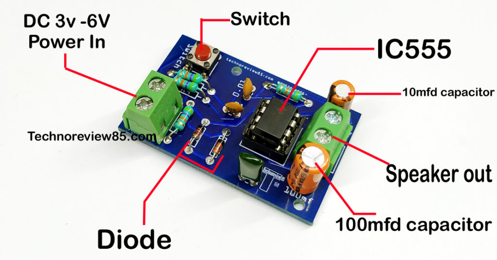
The assembling of components is very easy. All components value, polarity is printed in the PCB so just follow the printed components on the PCB. Use two terminal blocks for speaker connection & power.

About the circuit
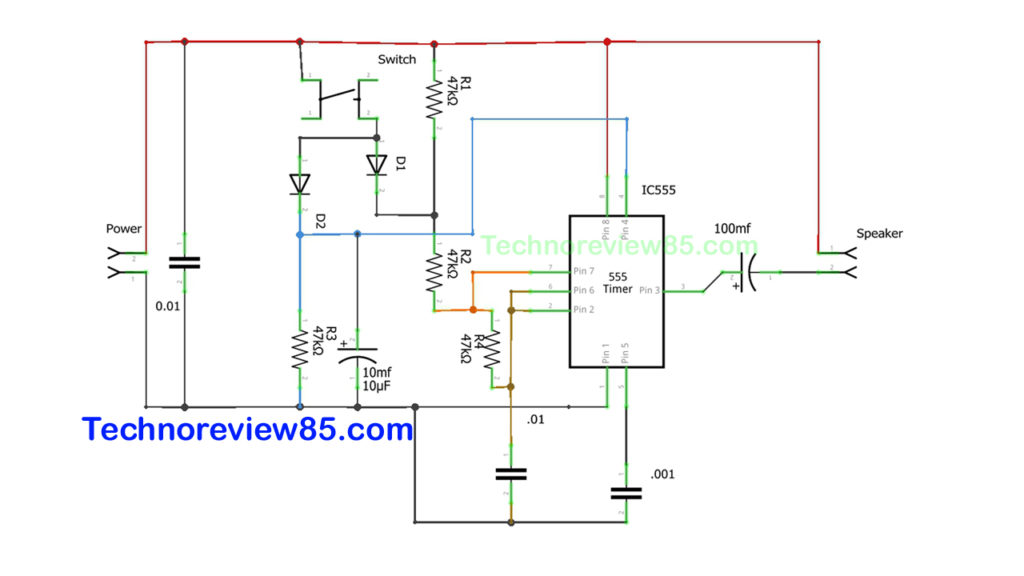
When the switch is pressed the circuit is working as an Astable Multivribator and its output changes cautiously between high & low states. The output in an Astable Multivibrator oscillates between two states at a constant rate. As a result, a square wave signal is given at its output. So we can hear a tone in speaker.
The schematic diagram of this project

Important note : –
Please use 3 volt to 6 volt DC to run the circuit. don’t use more 6volt otherwise, the IC may burn.
