
Esp 8266 01 is a popular wifi module.
It can works with AT commands with an Arduino. Also, it can be used as a standalone board like a microcontroller.
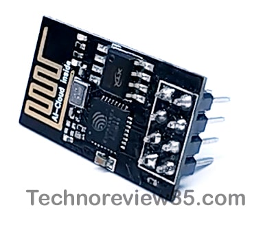
Its working voltage is 3.3v & it is very small in size so we can easily make our IoT based project using it.
It is a guide for programming the esp 01 module using an Arduino Uno board with Arduino ide software, sample led blink code & also discuss about some errors & its solution while programming.
How to connect esp8266 – 01 to Arduino Uno for programming
We have to connect the Esp 01 to Arduino Uno. You can make a temporary set-up on a breadboard. but you can’t use it directly on a breadboard so you have to use jumper wires. some times it is the reason for connection error.
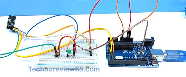
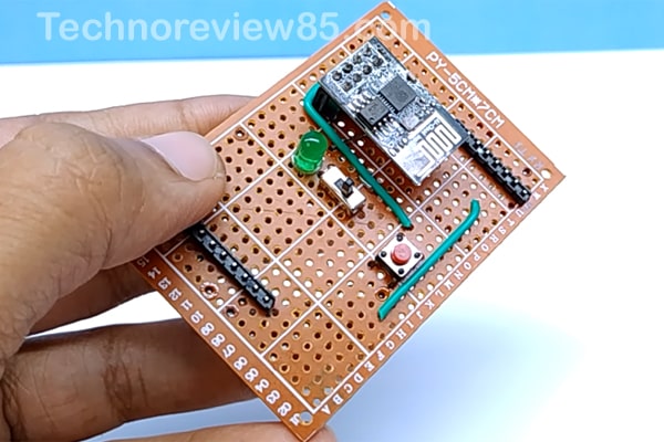
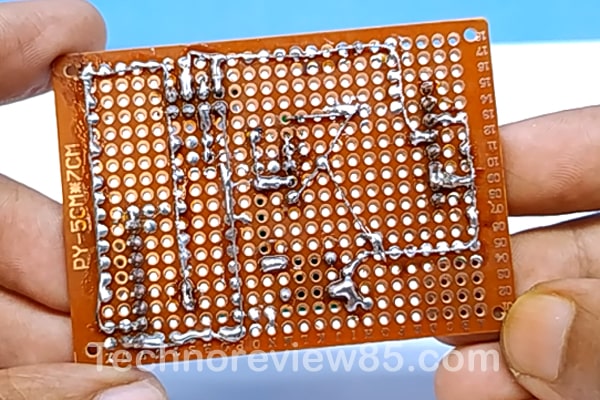
I made a shield for Arduino for avoiding every time jumper wire connection so making shield is a better option for programming every time without any problem.
Connection
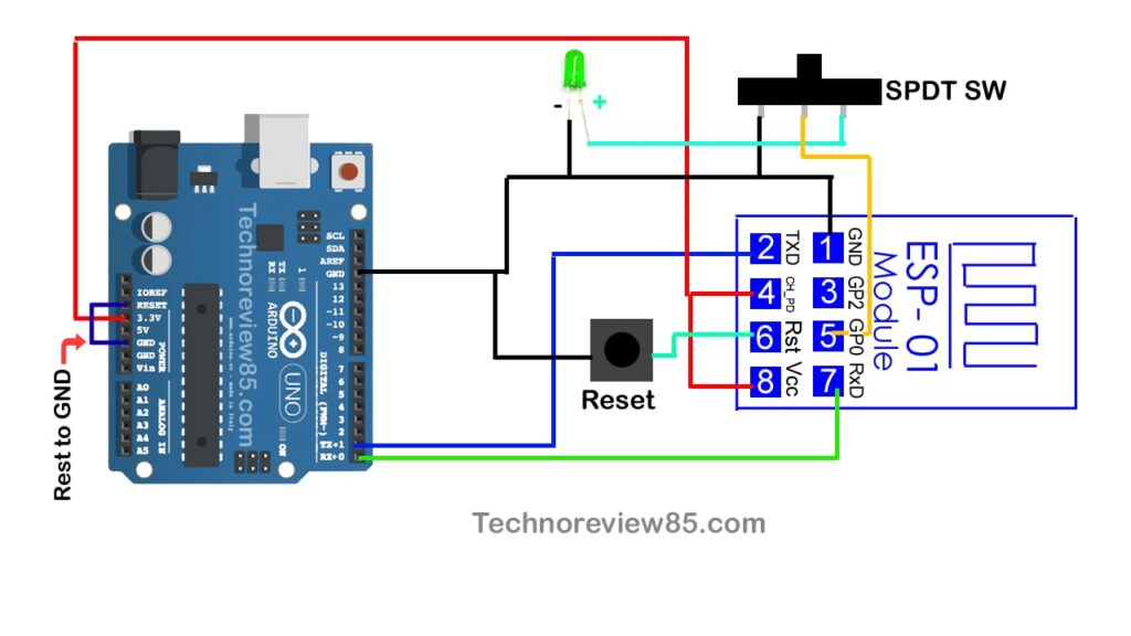
The Tx pin of Esp 01 connects to TX of Arduino Rx to Rx of Arduino.
Push switch connects to reset pin & GND pin of Esp 01.
Connect ChPD & VCC & connect to 3.3 volt of Arduino.
Connect ESP 01 GND to Arduino GND
The SPDT switch is connected to GPIO 0, Led + & GND.
To enable flash mode you have to connect Gpio 0 to GND so here I am using a switch to enable flash mode & working mode. This Led is for an indication.
And Arduino Rest pin connect to GND.

You need to make a shield
Male & female header pins
LED
Dotted board
Micro push Switch
Small SPDT switch
ESP 01 module
& Arduino Uno board
Programming Setup on Arduino IDE
Open Arduino Ide, go to – File – preference – paste this additional board
Manager URL.
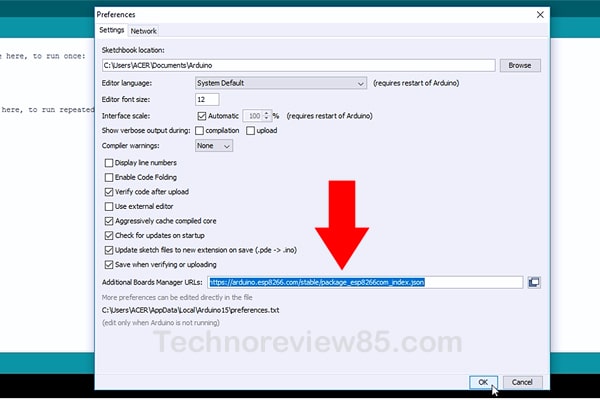
http://arduino.esp8266.com/stable/package_esp8266com_index.json
Click – ok
Now go to tools – Board – Board manager – search for Esp 8266.
I have already installed the board version 2.5.1 & it is working fine So I am not going to update it. You have to install it & then click on close.
Now connect the ESP 01 & Arduino to computer make sure the switch is on flash mode. If you have made a temporary setup then make sure GPIO 0 is connected to GND.
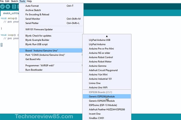
Now go to tools – select board generic Esp 8266 Module.
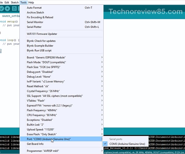
Go to tools – select your com port where Arduino is connected
Uploading sample LED blink code to ESP 01
Goto file – Example – Esp 8266 – Blink
Change this built in to 0 .
Our LED is connected to GPIO 0
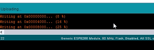
Now click on upload you can see the code is uploading
& complete.
Now change the switch position & push this reset button once.
Error during programming Esp8266 01 module
Sometimes it shows some connection error.
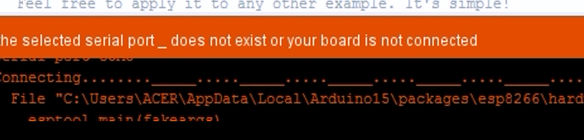
Solving the problems
1 check your connections
2 chek proper com port
3 chek gpio 0 is connected to GND
4 press the reset button once before showing connecting.
5 use a 220mfd electrolytic capacitor on VCC & GND of ESP 01.
This valuable message
did you connect the diode without a resistor?
not working pls help